_edited_edited.png)
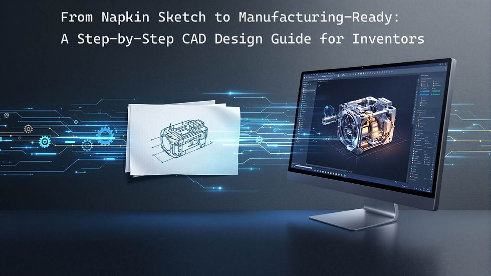
From Napkin Sketch to Manufacturing-Ready: A Step-by-Step CAD Design Guide for Inventors
- May 13, 2025
- 6 min read
So, you’ve got it – that brilliant flash of inspiration, the solution to a common problem, or a completely novel invention. Maybe it’s scribbled on a napkin, sketched in a notebook, or just crystal clear in your mind's eye. Congratulations! That initial spark is where every great product begins.
But how do you take that raw, exciting concept and turn it into something tangible, something that can actually be made? The journey from a simple idea to a product ready for the production line can seem daunting, but it's a well-trodden path. The crucial bridge in this journey is Computer-Aided Design (CAD).
This guide will walk you through the essential steps of transforming your napkin sketch into a manufacturing-ready CAD design, empowering you to bring your invention to life.
Step 1: Flesh Out Your Concept (Beyond the Napkin)
Before you even think about CAD software or designers, take time to develop your idea further. The clearer your concept, the smoother the design process will be.
Define the Core Problem & Solution: What specific problem does your invention solve? How does it solve it better than existing solutions (if any)?
List Key Features & Functionalities: What must your invention do? What are its essential components and how do they interact?
Identify Your Target User: Who will use your product? How will they use it? Understanding the user helps in making critical design decisions.
Expand Your Sketches: Move beyond the single napkin sketch. Create more detailed drawings from different angles. Add rough dimensions (even estimates are helpful at this stage) and make notes about materials or specific mechanisms.
Initial Research: Look into similar products. Are there existing patents for concepts like yours? Understanding the landscape can save you time and help refine your unique selling points.
The more information and thought you put in at this stage, the more effectively a CAD designer can translate your vision.
Step 2: Finding the Right CAD Design Partner (or Considering DIY)
With a more developed concept, you face a choice: attempt the CAD design yourself or hire a professional.
DIY CAD: Software like Fusion 360, SolidWorks, or FreeCAD are powerful, but they have steep learning curves and can be costly. If you have the time, technical aptitude, and a simpler design, this might be an option. However, be prepared for a significant time investment to become proficient, especially in creating designs optimized for manufacturing.
Hiring a Professional CAD Designer/Firm: For most inventors, especially those with complex ideas or who want to get to market efficiently, partnering with an experienced CAD designer or an engineering firm like DesignForge Engineering is the recommended route.
What to look for:
Experience: Especially with products similar to yours or in your target industry.
Portfolio: Review their past work to see the quality and complexity they handle.
Understanding of Manufacturing: A good designer doesn't just make pretty pictures; they design parts that can actually be made efficiently and cost-effectively.
Communication: You'll be working closely, so ensure they are good communicators and understand your vision.
Preparing for Consultation: Bring all your sketches, notes, research, and a clear explanation of your invention. The more prepared you are, the more productive your initial discussions will be.
Step 3: The Initial CAD Modeling Phase – Bringing it to 3D Life
This is where the magic starts to happen! Your chosen designer will take your sketches, notes, and discussions and begin translating them into a 3D digital model.
Basic 3D Model: The initial focus is usually on capturing the overall form, basic dimensions, and the arrangement of core components.
Visualization: For the first time, you'll see your invention as a 3D object on a screen. You can rotate it, look at it from any angle, and get a much better sense of its proportions and appearance.
Early Feedback & Iteration: This stage is highly collaborative. Your designer will likely share initial models for your review. Provide clear, constructive feedback. It’s much easier and cheaper to make changes to a digital model now than to a physical prototype or, worse, production tooling later.
Step 4: Detailed Design & Refinement – Adding the Nitty-Gritty
Once the basic form is established and approved, the design gets more detailed.
Specific Features: Moving parts, internal components, assembly mechanisms, ergonomic features, and aesthetic details are meticulously added.
Material Selection Considerations: While the final material choice might come later, the CAD model can be adapted for different material properties (e.g., strength, weight, flexibility). The design might need to change based on whether it's plastic, metal, or another material.
Tolerance Analysis: This involves defining acceptable variations in dimensions for each part to ensure they fit and function together correctly. It's crucial for assemblies.
Ergonomics & User Experience: How will the user interact with the product? Is it comfortable, intuitive, and safe? These factors are refined in the detailed design.
Multiple Iterations: Expect several rounds of review and refinement. This iterative process is key to honing the design and catching potential issues.
Step 5: Design for Manufacturability (DFM) – Ensuring It Can Be Made
This is a critical step that separates professional product design from hobbyist modeling. A design might look great on screen, but if it can't be manufactured efficiently and economically, it's not viable.
Manufacturing Process Consideration: The CAD model is reviewed and potentially modified based on the intended manufacturing process (e.g., injection molding, CNC machining, 3D printing, sheet metal fabrication). Each process has its own design rules and limitations.
DFM Examples:
For injection molding: Adding draft angles (slight tapers) so parts can be easily ejected from molds, ensuring uniform wall thickness to prevent defects, designing appropriate radii on corners.
For CNC machining: Considering tool access, minimizing complex setups, choosing appropriate tolerances.
For 3D printing: Optimizing orientation for strength and support material reduction.
Collaboration: Your CAD designer may collaborate with manufacturing experts or have this expertise in-house to ensure the design is optimized.
The Goal: DFM aims to reduce production costs, improve product quality, minimize assembly time, and speed up the overall manufacturing process.
Step 6: Prototyping from Your CAD Model – Testing the Waters
With a DFM-optimized CAD model, it's time to create physical prototypes.
Rapid Prototyping: Technologies like 3D printing are commonly used to quickly and relatively inexpensively create functional or visual prototypes directly from the CAD files.
Validation: Prototypes allow you to:
Test the fit, form, and function of your invention.
Assess ergonomics and user experience.
Identify any unforeseen design flaws or areas for improvement.
Gather feedback from potential users or stakeholders.
Iterate Again: Based on what you learn from the prototype, you'll likely go back to the CAD model to make further refinements. This iterative loop of CAD > Prototype > Test > Refine is common and valuable.
Step 7: Finalizing the CAD Package – Manufacturing-Ready Deliverables
After potentially several iterations and prototype evaluations, you'll arrive at a final, approved design. Your CAD designer will then prepare a "manufacturing-ready" CAD package. This typically includes:
Final 3D Models: These are the master digital files of your product and its components. Common file formats include STEP (.stp), IGES (.igs), or native CAD files (e.g., .sldprt for SolidWorks). Manufacturers use these for programming CNC machines, creating molds, or 3D printing production parts.
Detailed 2D Technical Drawings: These are formal engineering drawings derived from the 3D models. They include:
Precise dimensions for all features.
Tolerances (acceptable variations for each dimension).
Material specifications.
Surface finish requirements.
Assembly instructions (if applicable).
Notes for the manufacturer.
Bill of Materials (BOM): If your product is an assembly, a BOM lists all the individual components, parts, sub-assemblies, quantities, and sometimes supplier information.
This complete package provides manufacturers with all the information they need to accurately produce your invention.
Your Idea, Engineered for Reality
The journey from a napkin sketch to a manufacturing-ready CAD design is a systematic process of refinement, iteration, and expert application of design principles. While it requires diligence, partnering with experienced CAD professionals can demystify the process and significantly increase your chances of success.
By understanding these steps, you're better equipped to navigate the path from brilliant idea to a product that can truly make an impact.
Ready to take your invention beyond the napkin sketch? The team at DesignForge Engineering has over 20 years of experience helping inventors like you. Contact us today for a consultation, and let's discuss how we can bring your vision to life with expert CAD design and engineering services!


