_edited.png)
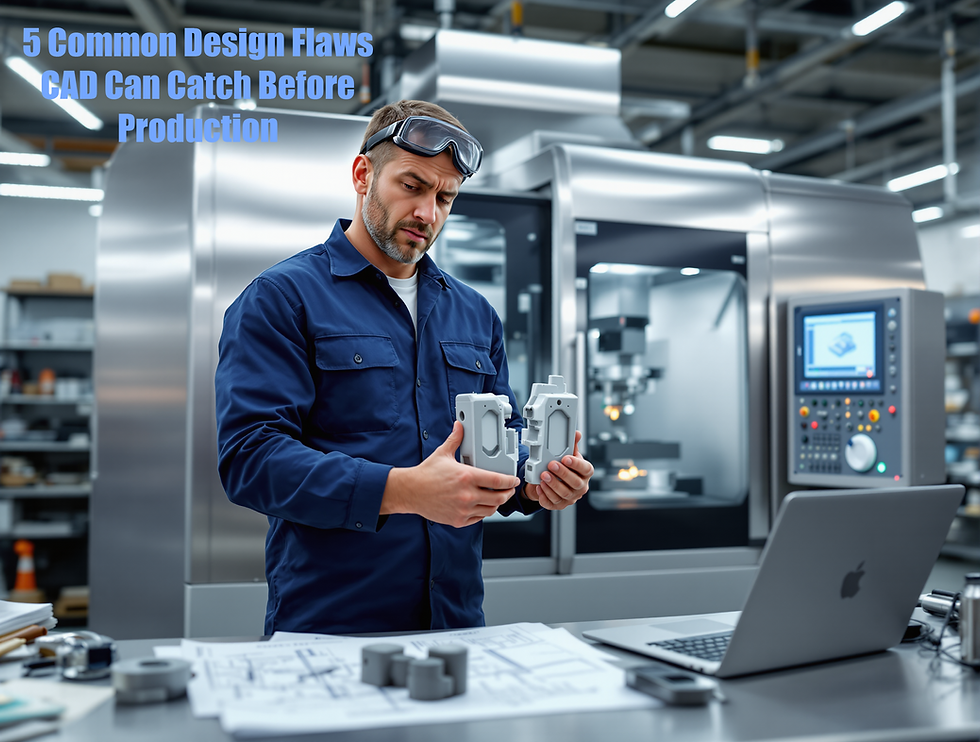
5 Common Design Flaws CAD Can Catch Before Production (Saving You Thousands)
- Nicholas Tamborello
- May 14
- 5 min read

In the fast-paced world of product development and manufacturing, catching design flaws early isn't just good practice; it's a financial lifesaver. The later a mistake is discovered in the production cycle, the more exponentially expensive it becomes to fix. Thankfully, Computer-Aided Design (CAD) software has evolved into a powerful ally, offering sophisticated tools to identify and rectify potential problems long before they hit the factory floor. Investing time in thorough CAD analysis can prevent costly retooling, material waste, production delays, and even product recalls. Let's explore five common design flaws that modern CAD systems are adept at catching, ultimately saving you significant resources.
Interference and Clearance Catastrophes
One of the most fundamental yet critical checks CAD performs is interference detection and clearance analysis. Imagine designing a complex assembly, like an engine or a piece of consumer electronics, with hundreds or even thousands of individual parts. Manually ensuring that no two parts occupy the same space or that there's adequate clearance for movement, assembly, or maintenance would be a herculean, error-prone task.
CAD software automates this by creating a 3D digital environment where all components can be assembled virtually. The software can then run checks to highlight any clashes (interferences) where parts are trying to pass through each other. It can also verify that specified clearances – for example, between a spinning shaft and its housing, or for a technician's hand to access a bolt – are met. Catching these issues in the digital realm prevents the nightmare of discovering on the assembly line that parts don't fit, requiring expensive redesigns, remanufacturing of components, and significant production delays. The cost of a single missed interference in a complex product can easily run into thousands, if not tens of thousands, due to scrapped parts and halted production.
Unmasking Manufacturability Mishaps (DFM)
A design might look brilliant on screen, but if it can't be manufactured efficiently and cost-effectively, it's fundamentally flawed. This is where Design for Manufacturability (DFM) principles, often integrated or supported by CAD tools, come into play. CAD software can help identify features that would be difficult, expensive, or even impossible to produce with standard manufacturing processes.
For instance, in injection molding, CAD can help analyze draft angles (the slight taper needed to eject parts from a mold), wall thicknesses (to prevent sink marks or incomplete fills), and the placement of ribs or bosses. For sheet metal parts, it can help optimize bend radii and ensure features are not too close to bends. For machined parts, it can highlight features requiring overly complex tooling or excessive machine time. By flagging these DFM issues early, designers can make adjustments that simplify production, reduce tooling costs, minimize scrap rates, and shorten lead times – all contributing to substantial savings. Ignoring DFM can lead to high per-unit costs, poor quality, and the need for expensive custom tooling or processes.
Exposing Structural Weak Spots with Simulation
Ensuring a product is strong enough to withstand its intended operational loads and environmental conditions is paramount. Over-engineering adds unnecessary material and weight (and thus cost), while under-engineering can lead to catastrophic failures, warranty claims, and damage to your brand's reputation. Modern CAD packages often include integrated Finite Element Analysis (FEA) or other simulation tools that allow designers to virtually test their designs under various stress conditions.
Designers can apply virtual forces, pressures, and thermal loads to their 3D models and see how the design responds. The software can pinpoint areas of high stress concentration, excessive deflection, or potential buckling. This allows for iterative design improvements, such as adding material where it's needed, removing it where it's not, or changing geometries to distribute loads more effectively. Catching a structural flaw before a physical prototype is even made, let alone before mass production, prevents the enormous costs associated with failed products, recalls, and potential liability. The savings here are not just in materials and manufacturing, but also in protecting against far greater post-sale expenses.
Tackling Tolerance Stack-up Troubles
In manufacturing, no part can be made to an absolutely perfect dimension; there will always be some variation. Tolerances define the acceptable range of variation for each dimension. When multiple parts are assembled, these individual variations can accumulate – a phenomenon known as tolerance stack-up. If not properly managed, this stack-up can lead to parts not fitting together correctly, or assemblies not functioning as intended, even if each individual part is within its specified tolerance.
Advanced CAD systems offer tolerance analysis tools that can simulate the effects of these variations across an entire assembly. By inputting the tolerances for each part, designers can predict the potential range of critical gaps or interferences in the final assembly. This allows them to identify critical dimensions that require tighter tolerances (which can increase manufacturing cost) and those where tolerances can be loosened (reducing cost) without impacting functionality. Catching tolerance stack-up issues in CAD prevents the costly scenario of assembling thousands of units only to find a significant percentage don't meet functional requirements, leading to rework, scrap, and diagnostic headaches.
Optimizing Material Selection and Usage
While CAD doesn't inherently choose materials, it provides an invaluable platform for evaluating the impact of different material choices on a design's performance, weight, and manufacturability. Designers can easily assign material properties (like density, tensile strength, thermal conductivity) to their 3D models. This allows for quick comparisons. For example, how does switching from steel to aluminum affect the overall weight and structural integrity? Can a less expensive grade of plastic still meet the performance requirements?
Furthermore, CAD tools, especially when combined with simulation, can help optimize the amount of material used. Topology optimization, for instance, is a powerful CAD-driven technique that removes material from areas where it’s not contributing to strength or stiffness, resulting in lighter, more efficient designs that still meet performance criteria. Reducing material usage directly translates to lower material costs, and lighter products can also mean lower shipping costs and potentially improved performance (e.g., better fuel efficiency in vehicles). Failing to optimize material selection and usage means leaving money on the table, either through over-engineered, heavy parts or by missing opportunities to use more cost-effective materials.
In conclusion, leveraging the full capabilities of modern CAD software is no longer a luxury but a necessity for competitive manufacturing. By proactively identifying and addressing these common design flaws in the digital stage, companies can avoid a cascade of expensive problems down the line. The initial investment in robust CAD tools and the time spent on thorough design validation pays for itself many times over by ensuring smoother production, higher quality products, and a healthier bottom line. Don't wait for the production line to reveal your design's weaknesses; let your CAD software do the heavy lifting upfront.


コメント